555 Timer Schematic Diagram : 555 Timer Integrated Circuit Symbol - Jul 14, 2015 · we can use this property of 555 timer to create various timer circuits like 1 minute timer circuit, 5 minute timer circuit, 10 minute timer circuit, 15 minute timer circuit, etc.
555 Timer Schematic Diagram : 555 Timer Integrated Circuit Symbol - Jul 14, 2015 · we can use this property of 555 timer to create various timer circuits like 1 minute timer circuit, 5 minute timer circuit, 10 minute timer circuit, 15 minute timer circuit, etc.. Between the positive supply voltage v cc and the ground gnd is a voltage divider consisting of three identical resistors, which create two reference voltages at 1 ⁄ 3 v cc and 2. Sep 29, 2015 · you can also calculate the t with this 555 timer monostable calculator. All we need to change the value of resistor r1 and/or capacitor c1. Dec 07, 2018 · 555 timer ic. For example, it can also generate frequencies to produce sound when the output is connected to a.
The 555 timer is a chip that can be us… We can use the 555 as a timer for up to 10 minutes. Above schematic diagram shows the 555 timer monostable multivibrator circuit. For example, it can also generate frequencies to produce sound when the output is connected to a. The control input is used in some of the applications, but most of the applications the control input is not used hence the control voltage is equal to +2/3 vcc.
Adjustable Timer Circuit using 555 from www.theorycircuit.com The astable mode is what most people think of when it comes to the 555 timer. Astable mode, monostable mode and bistable mode are the three modes of operation of ic 555. But it has a lot of other interesting applications too. 555 or 1/2 556 discharge control voltage threshold trigger reset r r r vcc output output sl00954 figure 1. Simple ne555 ic tester circuit diagram Jul 14, 2015 · we can use this property of 555 timer to create various timer circuits like 1 minute timer circuit, 5 minute timer circuit, 10 minute timer circuit, 15 minute timer circuit, etc. The internal block diagram and schematic of the 555 timer are highlighted with the same color across all three drawings to clarify how the chip is implemented: We need to set 555 timer in monostable mode to build timer.
You can explore various applications based on monostable multivibrator in 555 timer circuits.
The control input is used in some of the applications, but most of the applications the control input is not used hence the control voltage is equal to +2/3 vcc. This tutorial provides sample circuits to set up a 555 timer in monostable, astable, and bistable modes as well as an in depth discussion of how the 555 timer works and how to choose components to use with it. Sep 29, 2015 · you can also calculate the t with this 555 timer monostable calculator. This circuit is also called a delay. 555 ic timer block diagram 555 ic timer block diagram. Jul 02, 2020 · astable mode of the 555 timer. Learn by doing is the best. The block diagram of a 555 timer is shown in the above figure. Between the positive supply voltage v cc and the ground gnd is a voltage divider consisting of three identical resistors, which create two reference voltages at 1 ⁄ 3 v cc and 2. Jul 24, 2019 · the working principle of the 555 timer is by considering the block diagram of the 555 timer ic. The 555 timer is a chip that can be us… You can explore various applications based on monostable multivibrator in 555 timer circuits. The internal block diagram and schematic of the 555 timer are highlighted with the same color across all three drawings to clarify how the chip is implemented:
But it has a lot of other interesting applications too. The block diagram of a 555 timer is shown in the above figure. Simple ne555 ic tester circuit diagram The astable mode is what most people think of when it comes to the 555 timer. Jul 14, 2015 · we can use this property of 555 timer to create various timer circuits like 1 minute timer circuit, 5 minute timer circuit, 10 minute timer circuit, 15 minute timer circuit, etc.
The 555 timer schematic diagram | Download Scientific Diagram from www.researchgate.net You can explore various applications based on monostable multivibrator in 555 timer circuits. We can use the 555 as a timer for up to 10 minutes. All we need to change the value of resistor r1 and/or capacitor c1. The block diagram of a 555 timer is shown in the above figure. Simple ne555 ic tester circuit diagram This circuit is also called a delay. Astable mode, monostable mode and bistable mode are the three modes of operation of ic 555. Jul 02, 2020 · astable mode of the 555 timer.
In monostable mode, the duration for.
Simple ne555 ic tester circuit diagram The 555 timer is a chip that can be us… Above schematic diagram shows the 555 timer monostable multivibrator circuit. 555 or 1/2 556 discharge control voltage threshold trigger reset r r r vcc output output sl00954 figure 1. Many times when you see a project with flashing leds, it's a 555 timer at work. We can use the 555 as a timer for up to 10 minutes. The block diagram of a 555 timer is shown in the above figure. The control input is used in some of the applications, but most of the applications the control input is not used hence the control voltage is equal to +2/3 vcc. All we need to change the value of resistor r1 and/or capacitor c1. Astable mode, monostable mode and bistable mode are the three modes of operation of ic 555. Between the positive supply voltage v cc and the ground gnd is a voltage divider consisting of three identical resistors, which create two reference voltages at 1 ⁄ 3 v cc and 2. Resistive network consists of three equal resistors and acts as a voltage divider. This circuit is also called a delay.
The first comparator has threshold input to pin 6 and control inputs for pin 5. But it has a lot of other interesting applications too. You can explore various applications based on monostable multivibrator in 555 timer circuits. The block diagram of a 555 timer is shown in the above figure. Sep 29, 2015 · you can also calculate the t with this 555 timer monostable calculator.
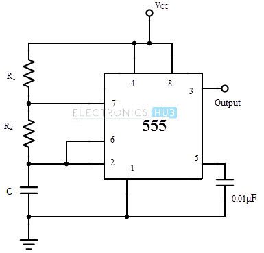
Astable Multivibrator Using 555 Timer from www.electronicshub.org Simple ne555 ic tester circuit diagram But it has a lot of other interesting applications too. Ic 555 timer ic is one of the most popular integrated circuit chip used for a variety of applications such as astable, monostable, bistable multivibrators, timer circuits, oscillators, pwm (pulse width modulation), ppm (pulse position modulation), square wave generator or pulse generator, etc. Apr 15, 2020 · people know it as the 555 timer ic. We need to set 555 timer in monostable mode to build timer. When the output is in a low state, the discharge transistor You can explore various applications based on monostable multivibrator in 555 timer circuits. Many times when you see a project with flashing leds, it's a 555 timer at work.
Ic 555 timer ic is one of the most popular integrated circuit chip used for a variety of applications such as astable, monostable, bistable multivibrators, timer circuits, oscillators, pwm (pulse width modulation), ppm (pulse position modulation), square wave generator or pulse generator, etc.
The block diagram of a 555 timer is shown in the above figure. The 555 timer is a chip that can be us… Many times when you see a project with flashing leds, it's a 555 timer at work. Jul 14, 2015 · we can use this property of 555 timer to create various timer circuits like 1 minute timer circuit, 5 minute timer circuit, 10 minute timer circuit, 15 minute timer circuit, etc. Astable mode, monostable mode and bistable mode are the three modes of operation of ic 555. Jul 02, 2020 · astable mode of the 555 timer. We can use the 555 as a timer for up to 10 minutes. You can explore various applications based on monostable multivibrator in 555 timer circuits. Simple ne555 ic tester circuit diagram Learn by doing is the best. Resistive network consists of three equal resistors and acts as a voltage divider. When the output is in a low state, the discharge transistor The astable mode is what most people think of when it comes to the 555 timer.
555 or 1/2 556 discharge control voltage threshold trigger reset r r r vcc output output sl00954 figure 1 555 timer schematic. This tutorial provides sample circuits to set up a 555 timer in monostable, astable, and bistable modes as well as an in depth discussion of how the 555 timer works and how to choose components to use with it.


0 Komentar